Science > Physics > Electromagnetic Induction > Rotation of a Coil in Uniform Magnetic Field
In this article, we shall study the rotation of coil in uniform magnetic field, the concept of alternating current.
The principle of Electrical Generator:
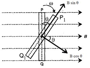
Consider a circular coil of ‘n’ turns of each area A placed with its plane perpendicular to a uniform magnetic field of induction B. At time t = 0, the plane of the coil is normal to field. Therefore, the magnetic flux passing through it is given by

ø = nAB.
Where n = number of turns
A = Area of the coil
B = Uniform magnetic induction
The coil is now rotated with constant angular speed ‘ω’ about a diameter. In a time ‘t’, the plane of the coil makes an angle θ with the initial position. Therefore, the angle traced by the coil in time ‘t’ is given by
θ = ωt
To find the new flux, the magnetic induction is resolved into two mutually perpendicular components. The component B sin θ is along the plane of the coil and hence it does not contribute flux. However, component B cos θ is perpendicular to the plane of the coil. Therefore, the flux through the coil at time t is given by
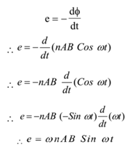
ø = nAB cos θ= nAB cos ωt
Therefore the induced e.m.f. in the coil is given by

Also ω= 2 π f, where f is the frequency of rotation.

Where e = instantaneous induced e.m.f.
e0 = peak e.m.f.
n = number of turns of the coil
A = Area of the coil
B = Uniform magnetic induction
Since sin ωt changes from +1 to -1, the e.m.f. induced changes periodically. The e.m.f. given by the above equation i.e. e = e0 sinωt is known as alternating e.m.f.
When sin ωt = ±1
e = e0 (±1) = ± e0 = Peak e.m.f.
The peak value of induced e.m.f. (e) is defined as the maximum value of alternating e.m.f.
Peak e.m.f. = e0 = 2πfnAB
Graphically an alternating e.m.f. e = e0 sin ωt is as shown. The graph shows that the induced e.m.f. changes its magnitude and direction periodically.

Simple A.C. Circuit With Resistance Only (Alternating Current):

Consider an A.C. Circuit consisting of a resistance R connected to a source of e.m.f.,
e = e0 sin ωt.
By Ohm’s law, the current through the circuit is given by,

Peak current (I0) is defined as the maximum value of alternating current.
Comparing the equations of A.C. e.m.f. and A.C. current it is obvious that they are in phase.

Terminology of AC Circuits:
Peak value of alternating e.m.f.:
The magnitude of the maximum value of alternating e.m.f. is called the peak value of e.m.f. It is denoted by e0.
Peak Value of Alternating Current:
The magnitude of the maximum value of alternating current is called the peak value of the current. It is denoted by I0.
Average value of Alternating e.m.f.:
The constant value shown by a D.C. voltmeter during one period of alternating e.m.f. (T) is called the average value of alternating e.m.f. It is denoted by eav. The average alternating e.m.f. is zero.
Average Value of Alternating Current:
The constant value shown by a D.C. ammeter during one period of alternating current (T) is called the average value of alternating current. It is denoted by Iav. As the average alternating e.m.f. is zero the average alternating current in the circuit is also zero.
R.M.S. Value of e.m.f.:
The root mean square (r.m.s.) value of e.m.f. is that steady e.m.f., which is to be applied across the given resistor to produce the same amount of heat in a given time as it is produced by given alternating e.m.f. It is denoted by er.m.s.
R.M.S. Value of Current:
The root mean square (r.m.s.) value of current is that steady current which is passed through given resistor to produce the same amount of heat in a given time as it is produced by given alternating current. It is denoted by Ir.m.s..
Expression for Power in AC Circuit:
An alternating current of peak value ‘I’ is equivalent to a constant direct current of value I0/√2. This is known as the effective value, virtual value or r.m.s. value of current.
Ir.m.s. = I0/√2
The power generated with the D.C. circuit containing resistance ‘R’ is given by
P = I2R
Therefore, the power generated in an A.C. circuit through which current Ir.m.s. is flowing through resistance ‘R’ is given by

But according to Ohms Law,

This is an expression for the power dissipated in A.C. circuit.