Science > Physics > Electromagnetic Induction > The Reactance of a Circuit
In this article, we shall study the concept of the reactance of inductive and capacitive circuits.
Concept of Reactance of a Circuit:
When A.C. current flows through a circuit, the resistance of the circuit opposes the flow of current. The circuit may contain other components like inductor or capacitor. These components also oppose the flow of current through them. This property of inductor and capacitor to oppose the flow of current is called reactance. The Reactance of inductor is called inductive reactance (XL) and that of the capacitor is called capacitive reactance (XC).
Reactance of a circuit is defined as the ratio of the r.m.s. voltage across the component to the r.m.s. current passing through it. Its unit is ohm.
Concept of Impedance of a Circuit:
An A.C. circuit may contain resistor, inductor and capacitor. Thus besides the resistance, the circuit has reactance. The combined effect of the resistance and reactance is called impedance (Z) of the circuit. The impedance of a circuit is defined as the ratio of r.m.s. the voltage across the circuit to r.m.s. current passing through it. The unit of impedance is ohm.
The Expression for Inductive Reactance:
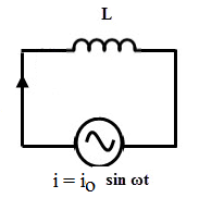
Consider a purely inductive circuit containing inductor only of inductance L. Let the inductor be connected across an A.C. source sending current i = io Sinωt. The instantaneous value of e.m.f. induced in the inductance due to alternating current is given by

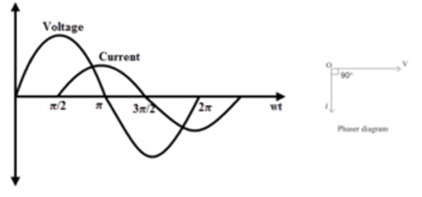
This equation shows that the induced e.m.f. in the inductor leads the current in the inductor by the phase of π/2. In other words the current in the inductor lags the e.m.f. induced in the inductor by the phase of π/2.

This is an expression for inductive reactance
The Expression for Capacitive Reactance:
Consider a purely capacitive circuit containing capacitor only of capacitance C. Let the capacitor be connected across an A.C. source sending current i = io Sinωt
Let the charge on capacitor be q and thus the potential difference across the capacitor is q/C. The rate of flow of charge is called the current
The total charge can be obtained by integrating the above expression.
But q = e C
This equation shows that the induced e.m.f. in the capacitor lags the current in the capacitor by the phase of π/2.In other words, the current in the capacitor leads the e.m.f. induced in the capacitor by the phase of π/2.
This is an expression for capacitive reactance
Expression for Power Dissipated in LCR Circuit:
Consider LCR circuit containing Resistance R, Inductance L and capacitance C connected in series. Let the combination be connected across an A.C. source of e.m.f. e = eo Sinωt. Let the phase difference between the e.m.f. and current be Φ. Therefore the instantaneous current is given by
i = io Sin (ωt ± Φ)
The sign of Φ is positive for capacitive reactance and negative for inductive reactance.
The instantaneous power in the circuit is given by
P = e I
∴ P = eo Sinωt. io Sin (ωt ± Φ)
∴ P = eo io Sinωt. [Sin ωt CosΦ ± Cos ωt Sin Φ]
∴ P = eo io. [Sin²ωt CosΦ ± Sinωt.Cos ωt SinΦ]
Therefore average power dissipated is given by
Knowing
The quantity cosΦ is called power factor of the circuit. The quantity e r.m.s. x I r.m.s. is called the apparent power.
The apparent power is calculated from the readings of voltmeter and ammeter connected in the circuit. If Z is the impedance of the circuit, then
The power factor, cosΦ = R / Z, Thus we have
True power dissipated in the circuit = Apparent power X Power factor.