Science > Physics > Elasticity > Behaviour of Ductile Material With Increasing Load
In this article, we shall study the construction and use of Searle’s apparatus to find Young’s modulus of wire and behaviour of ductile material of wire under increasing load.
Searle’s Experiment:
Apparatus :
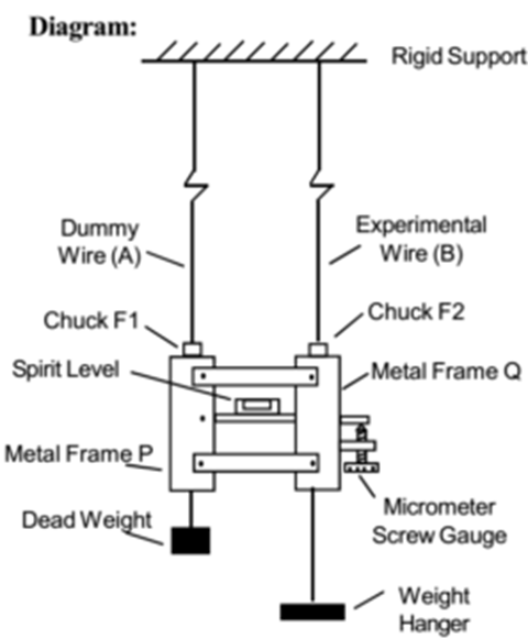
Two identical wires A and B are suspended from rigid support so that the points of suspension are very close to each other. Searle’s apparatus blocks are attached to the lower ends of the wires by means of chucks F1 and F2.
Searle’s apparatus block consists of two metal frames P and Q. The two frames are loosely connected by cross strips in such a way that the frame Q can move relatively with respect to frame P. A spirit level S is hinged to the frame P and is rested on the tip of a micrometer screw M which can work in a nut fixed in the frame Q. At the lower end, each frame carries a hanger from which slotted weights can be suspended. Wire A is a dummy wire from which a fixed load of about 1 kg (deadweight) is suspended.
Procedure:
- Initial readings and settings: Initially, the length (L) of wire B is measured. Its mean radius (r) is found with the help of a micrometer screw gauge. The wire A is experimental wire, it is initially subjected to a sufficient load called ‘zero load’ (about 1 kg) to avoid kinks in the wire. Micrometer screw is adjusted to bring the bubble in the spirit level at the centre and the reading is noted. This is called ‘zero reading’.
- Loading the wire: The load suspended from wire B is then increased in equal steps of about 0.5 kg-wt. let ‘m’ be the mass in the hanger. Each time, after waiting for about two minutes, the bubble is brought to the centre by rotating the screw and micrometer reading is noted. This is extension or elongation (l1) in the wire. This way five to six readings are taken.
- Unloading the wire: After loading procedure is complete the wire is unloaded in the same steps of 0.5 kg-wt and the readings ( l2) are noted again for each previous step.
Calculations:
The mean of the readings for loading ( l1) and unloading ( l2) is calculated and represented as (l) for each step. Then Young’s modulus of the material is calculated in each step using formula,

The average value of Young’s Modulus (Y) is calculated. Care should be taken to avoid possible errors.
Sources of Errors and Their Elimination:
- Error due to kinks in the wire: Initially, there may be kinks in the wire, if a load is attached at the free end the kinks will get straightened and observed elongation will be much greater than the actual elongation. To avoid such error sufficient weights are attached to remove all the kinks in the wire. This sufficient or adequate weight is called zero load.
- Errors due to a backlash of the screw: As we are using a screw gauge, there is a possibility of error due to backlash. This error can be eliminated by rotating the screw in one direction only when the load is increased and in the opposite direction only when the load is decreased.
- Error due to bending (yielding) of the support: If a single wire is used, and if the support from which the wire suspended bends, then the measured extension will be much greater than the actual extension in the wire. This error is eliminated by using dummy wire A. As both the wires are suspended from the same support, if the bending of support occurs, both wires will be lowered to the same extent and there will be no shift in the position of the bubble in the spirit level.
- Error due to thermal expansion or contraction: Since a long wire is used, a small change in temperature during the course of the experiment will produce a measurable change in length of the wire due to thermal expansion, then the measured extension will be greater than the actual extension in the wire. This error is eliminated by using a dummy wire. As both experimental wire and dummy wire are of the same material and same original length, the change in length due to change in temperature will be the same for both the wires and thus there will be no shift in the position of the bubble in spirit level.
- Error due to the crossing of the elastic limit and/or slipping of the wire from the chucks: If anyone or both these errors are present, the readings of the micrometer screw S while unloading will be different from the corresponding readings while loading. If the two sets of reading do not agree, then the experiment has to be repeated after tightening the chucks. Also, the maximum load to which the wire is subjected must be reduced.
Behaviour (Stress Strain Curve) of Wire of Ductile Material Under Steadily Increasing Load:
The behaviour of wire under increasing load can be studied using Searle’s apparatus. The wire whose behaviour is to be studied is used in the apparatus, at the free end, increasing loads are applied. For each load, stress and strain are calculated. Then the behaviour of wire is studied by plotting a graph, stress versus strain.

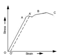
For ductile material, the graph is as shown. From O to A graph is a straight line which clearly indicates that the stress is directly proportional to strain, which indicates that Hooke’s Law is obeyed in this region. Point A is called the limit of proportionality.
The elastic limit is the point up to which Hooke’s law is applicable. Stress corresponding to this is called the elastic limit. If the load is removed before the elastic limit is crossed, then the wire will be able to recover its original length completely.
If the load is further increased, we get curve AA’ which indicates that Hooke’s law is not obeyed. The extension starts increasing faster than the load, and the graph bends towards the strain axis. If the wire is strained up to a point A’ and then if the load is removed, the wire is not able to recover its original length. However, the wire still retains its elastic properties. We can see it by the fact, that when the load is steadily reduced, a new straight-line graph such as A’O’ is obtained. In this case, the wire undergoes permanent deformation. The corresponding permanent strain OO’ is called a permanent set or permanent strain or residual strain.
If the load is increased further, a point B is reached, at which the tangent to the curve becomes parallel to the strain axis. It indicates that there is an extension in the wire without an increase in the load. Here wire exhibits plastic flow. The point B is called a yield point and corresponding stress is called yield stress.
Initially, as wire elongates area of cross-section decreases uniformly, but if the wire is loaded beyond point B, stress at some local point starts increasing rapidly due to neck formation in that region and ultimately wire breaks. This point is called the breaking point, and corresponding stress is called breaking stress or ultimate stress or ultimate strength.
For ductile material, there is neck formation at breaking point C. Before breaking ductile material always show plastic flow. For obtaining an appreciable extension of wire in Serle’s experiment, the specimen wire should be long and thin.
Important Points on the Stress-Strain Curve:
- Elastic limit: It is the maximum stress to which a body can be subjected without permanent deformation.
- Breaking Point: It is the point at which a body subjected to stress breaks (fails).
- Breaking Stress: The stress required to cause actual fracture of a material is called the breaking stress or the ultimate strength.
- Yield Point: It is the point at which the extension in a wire begins to increase even without any increase in load.
- Set: It is the permanent strain produced in a wire when it is stretched beyond the elastic limit.
Types of Material on Their Elastic Behaviour:
Ductile Materials:
Materials which have a great plastic range get stretched too long thin wires before they break are called ductile materials. Hence thin wires can be formed using ductile materials. e.g. steel, aluminium, gold, copper, silver, etc.
Brittle Materials:
Few materials break quite suddenly as soon as the stress-strain curve starts deviating from the straight line after the elastic limit. They are called brittle materials. Hence thin wires cannot be formed using brittle materials. e.g. glass, ceramics, cast iron, etc.
Related Topics:
- Classification of Materials
- Longitudinal Stress, Strain, and Young’s Modulus of Elasticity
- Numerical Problems on Stress, Strain, and Young’s Modulus of Elasticity
- Numerical Problems on Poisson’s ratio
- Numerical Problems on Compound Wires
- Volumetric Stress, Volumetric Strain, and Bulk Modulus of Elasticity
- Shear Stress, Shear Strain, and Modulus of Rigidity
- Strain Energy