Science > Physics > Interference of Light > Concept of Fringe Width and Path Difference
In this article, we shall study Young’s double-slit experiment to demonstrate interference of light and also derive expressions for path difference and fringe width.
Young’s Double Slit Experiment:
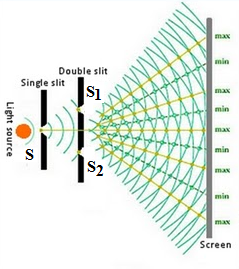
The Young’s double-slit experimental arrangement consists of a pinhole ‘S’ punched on cardboard arranged in a dark room. The pinhole is illuminated by a beam of sunlight. The emergent light is allowed to fall on two more symmetrical pin holes S1 and S2 close to each other. These two pinholes act as two coherent sources and give rise to secondary spherical wavefronts. The light emerging from S1 and S2 produces a steady interference pattern on a screen kept at a large distance away from them. The interference pattern consists of alternately bright and dark ‘bands. As sunlight consists of a large number of wavelengths the interference bonds are coloured as indistinct.
A modified Young’s experiment known as Young’s double-slit experiment gives rise to a sharp and clear Interference pattern. In this, sunlight is replaced by a monochromatic source of light and pin holes are replaced by narrow slits parallel to each other. The interference pattern obtained on the screen consists of well-defined alternate bright and dark bands. These bands are of equally spaced and are called interference bands or fringes.
Significance of Young’s Double Slit Experiment:
- Double slit experiment was the first experiment to demonstrate interference of light
- It gave the experimental confirmation of the wave nature of light.
Expression for Fringe Width of Interference Band:
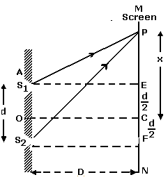
Let S1 and S2 be two coherent thin sources (in form of slits) of monochromatic light. ‘d’ be the distance between them. Let ‘D’ be the distance of a screen from the sources kept parallel to the plane of the coherent sources; (D is large compared to d). Light waves emitted from the sources interfere and produce a stationary interference pattern on the screen which consists of alternately bright and dark fringes. Let OC be the perpendicular bisector of S1S2 and P be a point on the screen such that CP = x. Draw S1E and S2F perpendicular to the screen.
For point C, x = 0 Thus, path difference = 0; so the point B will be a bright point. Hence interference fringe situated at C will be a bright fringe known as the central bright fringe. On either side of central bright fringe alternate dark and bright fringes will be situated. This set of bright and dark fringes is called an interference pattern.

Subtracting equation (2) from (1)
But S2P – S1P is the path difference between the light waves reaching point P.
Hence path difference = xd/D …… (3)
Now we know that the brightness or darkness of a point depends upon the path difference. If path difference = n λ, where n = 0,1,2,3,….. the point will be bright and if path difference = (2n – 1)( λ /2), where n = 1,2,3,…. the point will be dark.
The distance between two consecutive dark bands or consecutive bright bands in an interference pattern is called the fringe width.
For Bright Fringe:
For bright band Path difference = n λ
∴ xd/ D = n λ
Let xn be the distance of nth bright fringe from the central bright fringe. Let xn+1 be the distance of (n + 1)th bright fringe from the central bright fringe.
But we know that the fringe width is the distance between two consecutive bright (or dark) fringes. Let X be the fringe width.
For Dark Fringe :
For dark band path difference = (2n – 1)( λ /2)
Let xm be the distance of mth dark fringe from the central bright fringe. Let xm+1 be the distance of (m + 1)th dark fringe from the central bright fringe.
From equation (5) and (6) we can conclude that the distance between two consecutive bright bands is the same as the distance between two consecutive dark bands. Thus the bright band and dark band are alternate and are equally spaced.
Fresnel’s Biprism experiment:
Principle :
Fresnel’s Biprism method gives rise to a well-spaced and sharp interference pattern. A biprism consists of a triangular prism having a very large refracting angle (or two identical wedge-shaped prisms of small acute angle joined with their bases in contact).
The biprism is held symmetrically with its refracting edge parallel to the slit. The slit is illuminated with monochromatic light of wavelength λ. The divergent beam of light from the slit is incident on the biprism. One biprism then produces two virtual images S1 and S2 of the slit S, which then acts as coherent sources of light at a small distance ‘d’ apart. The interference fringes are obtained in the focal plane of the micrometer eyepiece E.
Apparatus:
The biprism experiment is performed by using an optical bench. It consists of a heavy metal platform of about 2 metre long and provided with a scale along its length. The optical bench is fitted with four adjustable vertical stands which can be moved along the length of the bench. The stands support a slit, biprism, convex lens, and a micrometer eyepiece.
Adjustments:
The slit S is made narrow and is illuminated by light from a monochromatic source of wavelength λ kept behind it. The light emerging from the slit is allowed to fall on the biprism B with its edge parallel to the slit.
The eyepiece. is kept at a sufficiently large distance D from the slit. The slit, refracting edge of the biprism and the crosswire of the eyepiece are arranged parallel to each other in the same straight line. By looking through the eyepiece, the biprism is slowly rotated about a horizontal axis. When its edge becomes exactly parallel to the slit, interference pattern consisting of alternate bright and dark bands can be seen through the eyepiece.
Measurements:
The wavelength of monochromatic light is given by the formula where
X = λD/d
Where d = distance between two coherent sources.
D = distance between the slit and the focal plane of the eyepiece
Measurement of D:
D between the plane of the slit and the focal plane of the micrometer eyepiece can be directly measured from the scale marked at the edge of the optical bench.
For a given adjustment, reading corresponding to the reference marks on the bases of vertical stands carrying slit and eyepiece are noted. The difference between the two readings gives D.
Measurement of X:
To measure fringe width X, the micrometer screw is so adjusted that, the cross wire of it coincides with one bright band. The micrometer reading x1 is noted. By rotating the screw, the cross wire is made to coincide with successive bright bands and corresponding reading x2, x3, x4, x5, ….etc. are noted. The average difference between two successive readings such as | x2 – x1|, | x3 – x2 |, |x4 – x3 |,…… etc. gives the mean fringe width.
Measurement of ‘d’ :
To measure ‘d’ a convex lens mounted on the stand kept between the biprism and the eyepiece, without disturbing the slit and the biprism, the eyepiece is moved in such a way that the distance between the slit and the eyepiece is more than four times the focal length of the lens. One lens is moved towards the slit and its position (L1) is so adjusted that two magnified images of the slit are seen through the eyepiece.
By adjusting the eyepiece, its cross wire is made to coincide with each image and corresponding micrometer readings are noted. The difference between the readings gives the distance d between the two magnified images.
By the principle of linear magnification
d1/d = v /u …….. (1)
The convex lens is now moved towards the eyepiece and its position (L2) is adjusted so that two diminished images of the slit are seen through the eyepiece.
By adjusting the eyepiece, its cross wire is made to coincide with each image and corresponding micrometer readings are noted. The difference between the readings gives the distance ‘d’ between the two diminished images.
By the principle of conjugate focii
d2/d = u /v …….. (2)
The wavelength of monochromatic light can be calculated using the formula X = λD/d
Previous Topic: Numerical Problems on Formation of Bright and dark bands
Next Topic: Numerical Problems on Fringe Width and Change of Fringe Width