Science > Physics > Current Electricity > Kirchhoff’s Laws
In this article, we shall study Kirchhoff’s laws, construction, working and uses of Wheatstone’s metre bridge. There are two Kirchhoff’s laws viz: current law or junction law and voltage law or mesh law.
Kirchhoff’s Current Law or Kirchhoff’s Junction Law:
Statement:
In an electric network, the algebraic sum of currents at any junction is zero.
Explanation:
Any point in the circuit where the current split is called a junction. Currents approaching junction are taken positive and currents going away from junction are taken as negative. Let us consider a junction of a circuit as shown in the figure.
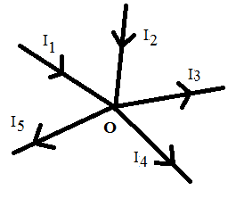
Applying Kirchhoff’s junction law at point O.
I1 + I2 – I3 – I4 – I5 = 0
Since there is no loss or gain of the charge at the junctions, this law is in accordance with the law of conservation of charge.
Kirchhoff’s Voltage Law OR Kirchhoff’s Mesh Law:
Statement:
The algebraic sum of the products of the current and resistance of each part of a closed circuit (mesh or loop) is equal to the algebraic sum of the e.m.f.s in that closed circuit.
Sign Convention:
- When passing through the circuit in the direction of current there is drop in the potential hence the potential difference should be taken as negative.
- When passing through the circuit in the opposite direction of current there is an increase in the potential hence the potential difference should be taken as positive.
- When passing through a cell from the negative terminal to the positive terminal the e.m.f. of a cell is taken as positive.
- When passing through a cell from the positive terminal to the negative terminal the e.m.f. of a cell is taken as negative.
Explanation:
Consider the following circuit
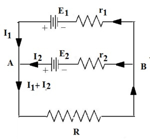
Let us consider a closed-loop E1ARBr1
E1 – (I1 + I2) R – I1r1 = 0
Let us consider a closed-loop E2ARBr2
E2 – (I1 + I2) R – I2r2 = 0
Let us consider a closed-loop E1AE2BE1
E1 – E2 + I2r2 – I1r1 = 0
Wheatstone’s Network (Application of Kirchhoff’s Laws):
Circuit Arrangement:
A Wheatstone’s network consists of four resistances connected such that they form a quadrilateral of resistances. A battery is connected (or p.d. is applied) between one pair of opposite corners of the quadrilateral. A galvanometer is connected between another pair of opposite corners.

When the values of the resistance are such that, the galvanometer shows no deflection or null deflection then the network is said to be balanced Wheatstone’s network.
Condition for Balanced Wheatstone’s Network:
Let R1, R2, R3, and R4 be the four resistances connected as shown in the diagram to form Wheatstone’s network as shown in the diagram. Let I1, I2 be the currents through the resistances R1 and R3 respectively. Let IG be the current through the galvanometer whose resistance is G. In balanced condition the current through galvanometer is zero hence IG = 0
Applying Kirchhoff’s voltage law to the loop ABDA,
I1R1 –IGG + I2R3 = 0
∴ – I1R1 –(0) G +I2R3 = 0
∴ – I1R1 + I2R3 = 0
∴ I1R1 = I2R3 ……….. (1)
Applying Kirchhoff’s voltage law to the loop BCDB
– (I1 – IG) R2 + (I2 + IG) R4 + IGG = 0
∴ – (I1 – 0)R2 + (I2 +0)R4 + (0)G = 0
∴ – I1 R2 + I2R4 = 0
I1 R2 = I2R4 …….. (2)
Dividing equation (1) by (2)
This is the required condition for balanced Wheatstone’s network.
Condition for Balanced Wheatstone’s network using Ohm’s law:
When the values of the resistance are such that, the galvanometer shows no deflection or null deflection then the network is said to be balanced Wheatstone’s network. Thus potential at point B is equal to the potential at D. Thus (VB = VD)
∴ VA – VB = VA – VD
∴ By Ohm’s law I1R1 = I2R3 ……… (1)
Similarly VB – VC = VD – VC
∴ By Ohm’s law (I1 – IG)R2 = (I2 + IG)R4 ……… (2)
But no current flows through the galvanometer (IG = 0)
I1R2 = I2R4 ……… (2)
Dividing equation (1) by (2)
This is the required condition for balanced Wheatstone’s network.
Wheatstone’s Metre Bridge:
The value of an unknown resistance can be determined by using Wheatstone’s meter bridge.
Construction:
It consists of a uniform wire AC, one meter long, stretched on a wooden board. The two ends of the wire are fixed to two thick L shaped copper strips. The third thick and straight copper strip is so put that it forms two gaps with the two copper strips.
The unknown resistance X is connected in one gap and a resistance box R (known resistance) is connected in the other gap. The junction of X and R is connected to one terminal of a galvanometer G. The other terminal of the galvanometer is connected to a pencil Jockey which can slide along the wire AC. A cell, key, and rheostat are connected in series with the wire.
Working:
A suitable resistance R is taken in the resistance box and the current is sent around the circuit by closing the key K. The jockey is touched to different points of the wire AC and a point of contact D for which the galvanometer shows zero deflection is found. As at point D the galvanometer is showing null deflection, point D is called the null point.
Let the distance of the point from A be l1 and that from C is l2. These two distances are measured. Let σ be the resistance per unit length of wire. As the network is balanced
Using this formula unknown resistance X can be calculated.
Possible Errors in Metre Bridge Experiment:
- If the wire is not uniform, the resistance per unit length of wire is not the same throughout the wire and thus there is a possible error in the determination of unknown resistance.
- There may be the error due to contact resistances of the points where the wires are connected to copper strips.
Minimization of Errors:
- The resistance X and R are interchanged and experiment is repeated.
- Value of R is so selected that the deflection in the galvanometer is at the centre of the scale.
- The average of the readings of a number of readings gives most probable value.
Kelvin’s Method to Find Resistance of a Galvanometer:
By this method, the resistance of galvanometer itself can be found.
Circuit Arrangement:
The galvanometer whose resistance to be found is connected in one gap and the known resistance R is connected in another gap. The galvanometer itself is used to determine the condition of equilibrium without locating null point. The junction of galvanometer G and known resistance R is connected to the jockey.
The circuit is closed and adjusting the rheostat a suitable current is passed through the circuit. A suitable resistance is taken out from the resistance of the box and deflection in the galvanometer is noted. A jockey is moved over wire AC. A point D is noted for which the galvanometer shows the same deflection as before. Thus D point is such that at this point the deflection is the same with or without the jockey. Thus D is equal deflection point.
Distances of point D from two ends are measured. Let AD = l1 and CD =l2. If G is the resistance of the galvanometer, then using the following formula the value of G can be calculated.
Previous Topic: Temperature Dependence of Resistance
Next Topic: Numerical Problems on Metre Bridge