Science > Physics > Current Electricity > Potentiometer
In this article, we shall study the principle, construction, and working of a potentiometer and its uses.
Principle of Potentiometer:
When a steady current flows through a wire of uniform cross-section the potential difference per unit length of the wire is constant throughout the length of the wire (or p.d. across any two points of the wire is directly proportional to the length of the wire. It can be explained as below.
Let us consider a uniform wire AB of length lAB and uniform cross-sectional area A. Let RAB be its resistance. Let ‘I’ be the steady current flowing through the wire. Let VAB be the p.d. across the ends of the wire. Let ‘ρ be the specific resistance of the material of the wire. Let there be a uniform potential drop across the length of wire.
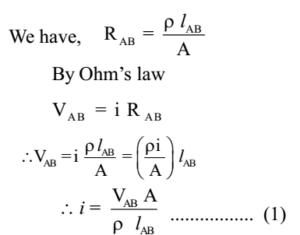
Let us consider point P on the wire and the length of wire between A and P be ‘ lAP’. Thus, the resistance of a wire of length ‘RAP’ is given by

When a constant current flows through a wire, then the potential difference between any two points of the wire is directly proportional to the length of wire between these two points. In such a case, the p.d. per unit length of the wire is constant and called the potential gradient of the wire or voltage drop across the wire.
Precautions to be Taken While Using a Potentiometer:
The e.m.f. of the cell connected across the potentiometer wire should b greater than the e.m.f. to be compared.
The positive terminal of the cells whose e.m.f. is to be compared must be connected to that end of potentiometer wire where positive terminal of the battery (driving cell) is connected.
The potentiometer wire must be uniform.
The resistance of potentiometer wire should be high.
Advantages of a Potentiometer Over a Voltmeter:
- A potentiometer can be used to measure the internal resistance of cell which cannot be measured by the voltmeter.
- A Potentiometer can be to measure e.m.f of a cell which cannot be measured by a voltmeter. When a voltmeter is connected in a circuit it draws current through the circuit and thus can measure the potential difference across the cell terminals. When the potentiometer is connected in a circuit it draws no current when the null point is obtained. Thus it measures the e.m.f. of the cell.
- A potentiometer can be used to measure extremely small p.d. accurately which cannot be measured by a voltmeter. It can be done by using very long wire and adjusting a very small potential gradient.
- Potentiometer is more sensitive compared to voltmeter.
- The accuracy of the potentiometer can be increased by increasing the length of the wire. The accuracy of the voltmeter cannot be increased beyond the limit.
Disadvantages of a Potentiometer:
- A voltmeter is a direct reading instrument while potentiometer is not so. We have to perform calculations to find the result.
- A voltmeter is portable while potentiometer is non-portable
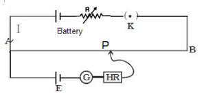
Construction of Potentiometer:
A potentiometer consists of a uniform wire AB several meters long. It is stretched between two points A and B on the wooden board. A battery having a sufficiently large e.m.f. E is connected between A and B of the wire. On closing, the key current will flow through the wire. The current in the wire can be adjusted by adjusting rheostat connected in series with the battery. The battery maintains a uniform potential gradient along the length of wire.
Uses of Potentiometer:
To Measure e.m.f. of a Cell or to Compare e.m.f.s of Two Cells by Individual Method
Let E1 and E2 be the e.m.f.’s of the two cells to be compared by using the potentiometer. The positive terminal of the cell of e.m.f. E1 is connected to end A and a negative terminal is connected to jockey through the galvanometer. By closing the key the jockey is moved along wire AB and null point P is determined such that galvanometer shows no deflection. The length of wire AP = l 1 is measured. The p.d. across this length balances e.m.f. E1
e.m.f. of the cell = potential difference across AP
E1 = K l1 ……….. (1)
where K is the Potential gradient of the wire
Then cell of e.m.f. E1 is disconnected and cell of e.m.f. E2 is connected in circuit and procedure is repeated
E2 = K l2 ……….. (2)
Dividing equation (1) by (2), we get,
Thus knowing the values of l1 and l2 we can compare e.m.f.s of two cells.
To Measure e.m.f. of a Cell or to Compare e.m.f.s of Two Cells by Sum and Difference Method:
Let E1 and E2 be the e.m.f.’s of the two cells to be compared by using the potentiometer. In this method both the cells whose e.m.f.s are to be compared are connected together.
When the two cells are connected in series such that the negative terminal of one cell is connected to positive terminal of the other, then the two cells are said to assist each other and their resultant e.m.f. is given by the sum of the e.m.f.s of the two cells. (E1 + E2)
When the two cells are connected in series such that the negative terminal of one cell is connected to the negative terminal of the other, then the two cells are said to oppose each other and their resultant e.m.f. is given by the difference of the e.m.f.s of the two cells. ( E1 – E2)
In the first step, the cells are connected to assist each other. The positive terminal of the combination of cells is connected to end A and another terminal is connected to jockey through the galvanometer. By closing the key the jockey is moved along wire AB and null point P is determined such that galvanometer shows no deflection. The length of wire AP = l1 is measured. The p.d. across this length balances e.m.f. (E1 + E2)
∴ e.m.f. of the cell = potential difference across AP.
E1 + E2 = K l1 . . . (1)
where K is the Potential gradient of the wire
In the second step, the cells are connected to oppose each other and the procedure is repeated.
E1 – E2 = K l2 . . . (2)
Dividing equation (1) by (2), we get,
Thus knowing the values of l1 and l2 we can compare e.m.f.s of two cells.
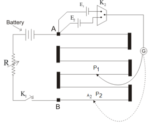
To Find Internal Resistance of a Cell:
A battery B having an e.m.f. greater than the e.m.f. (E) of the cell whose internal resistance (r) is to be measured, is connected in series with the potentiometer wire AB, a key K1, and a rheostat. The positive terminal of the cell of e.m.f. E is connected to the end A of the potentiometer wire. The negative terminal of E is connected to a jockey through the galvanometer G. A resistance box and a keyK2 are connected across the cell E.
Initially, the key K2 is kept open. By closing the key K1 current is passed through the potentiometer wire so that uniform potential gradient is produced along the wire. By sliding the Jockey along the wire, a point of contact P1 for which the galvanometer shows zero deflection is found. The length of the wire AP1 = l is measured. As the cell is in an open circuit, e.m.f. of the cell is equal to the p.d. across the length l, of the potentiometer wire.
E = K l . . . (1)
Where K is the potential gradient of the wire.
Now a suitable resistance (R) is connected from the resistance box and the key K2 is closed and once again null point P2 is found on the potentiometer wire. The length AP2 = l1 is measured. Let V be the terminal p.d. of the cell
Thus knowing R, l and l1 we can calculate the value of r i.e. the internal resistance of the cell using this formula.
Previous Topic: Numerical Problems on Metre Bridge
Next Topic: Numerical Problems on Potential Drop (Potentiometer)
2 replies on “Potentiometer”
it better
Very useful