Science > Physics > Electromagnetic Induction > Resonating Circuit
In this article, we shall study resonating circuit: a) LCR Series Circuit and b) LC parallel circuit.
Series Resonating Circuit:
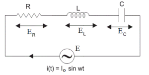
Consider LCR circuit containing Resistance R, Inductance L and capacitance C connected in series. Let the combination be connected to an A.C. source supplying current i = io Sinωt.
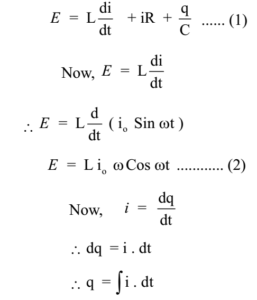
The instantaneous e.m.f. of the circuit is equal to the sum of voltage drops across the resistor, the capacitor, and the inductor.
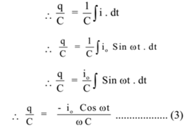
Dividing both sides of the equation by C

Substituting the values of equations (2) and (3) in equation (1)
Substituting these values in equation (4) we have
Thus the e.m.f. leads the current in phase given by
In this condition the impedance of the circuit is minimum and the circuit acts as a purely resistive circuit. The current in the circuit is maximum. This condition is called a series resonance of the circuit. At resonance
The frequency fr is called the resonating frequency. The frequency at which the resonance takes place and the maximum current flows through the circuit is called the resonating frequency.
The variation of the current with frequency for the series LCR circuit is as shown in the graph.
Parallel Resonating Circuit:
Consider LC circuit containing Inductance L and capacitance C connected in parallel. Let the combination be connected to an A.C. source with e.m.f. e = eo Sin ωt.
The current in the inductance lags behind the e.m.f. by π/ 2. Thus the current through the inductance is given by
Where, XL = Inductive reactance
The current in the capacitance leads the e.m.f. by π/ 2. Thus the current through the inductance is given by
Where XC = Capacitive reactance
The total current in the circuit is given by
When XL = XC i.e. ωC = 1/ ωL , the current in the circuit is zero. This condition is called parallel resonance of the circuit.
At resonance
The frequency fr is called the resonating frequency. The frequency at which the resonance takes place and the zero current flows through the circuit is called the resonating frequency. At resonating frequency the impedance is maximum.