Science > Physics > Communication > Communication Channel: Line
Line Communication:
Space communication is unguided communication. In this communication channel, there is no physical contact between the transmitting and the receiving antenna. The transmitted signal spreads in all directions. This results in the attenuation of the signal. To avoid the attenuation we use line communication. Inline communication, the signal is transmitted from the transmitter to the receiver through a connecting wire. This communication system requires a solid medium as the communication channel between the transmitter and the receiver. This medium is called a transmission line. This is the oldest method of transmission. The principal type of such communication are:
- two-wire transmission lines
- coaxial cables and
- optical fibres.
Two-wire transmission lines and coaxial cables are used to transmit AF and UHF signals while optical fibres are used to transmit optical signals. At high-frequency two-wire transmission lines are affected by electromagnetic interference and radiation. This disadvantage of the two-wire transmission line is avoided by using a shield in coaxial cables.
Two-wire transmission line:
In this case, the electrical signal is passed through a pair of conducting wires insulated from one another. The most commonly used two-wire transmission lines are i) parallel wireline and twisted wireline
Parallel Wire Lines:
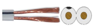
It consists of two metallic wires arranged parallel to each other inside an insulating coating. The metal wires are hard or flexible depending on the power transmitted. Hardwires are used for high power transmission. In this transmission line, it is necessary to match the impedance of the wire with that of the receiver to obtain a maximum transfer of power.
The losses increase with the increase in the length of the wire and the frequency of the transmitted signal. Thus, parallel wire lines are used to send low-frequency electrical signals over small distances. Parallel wires are commonly used to connect the antenna to a T.V. receiver.
Twisted Wire Line:
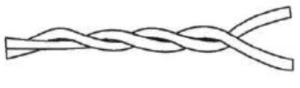
It consists of two insulated copper wires twisted
around each other at regular intervals of distance to minimize electrical
interference.
They are used to transmit both digital and analog signals. A twisted pair
of lines is inexpensive and easy to install. They are commonly used to connect
telephone systems.
Coaxial Cable:

It consists of a Central copper wire surrounded by a PVC (dielectric) insulation and then is covered by a copper wire mesh. A tinned copper wire mesh (braided shield) is covered by an outer shield of thick PVC material. The signal is transmitted through the central copper wire while the outer conductor is connected to the ground. The material like Teflon and polyethene are used as dielectric insulation depending upon frequency and power to be transmitted through the cable. the grounded outer shield provides an electrical shield to the signals carried by the central conductor. The outer PVC jacket prevents inner copper wire or core from radiating signal, power. Thus it reduces losses. The characteristic impedance of coaxial cables is 50 ohms to 75 ohms.
Communication through a coaxial line is more efficient than two-wire lines as the attenuation of the signal is low. However, they are expensive as compared to two-wire lines. If the frequency to be transmitted is more than 20 MHz, there are considerable dielectric losses through the dielectric insulator. Hence this puts a limit to the frequency to be transmitted.
Due to higher bandwidth, the coaxial cable can transmit digital data at a much higher rate of up to 20 Mbps. but the rate of 10 Mbps is standard Co-axial Cables are used to transmit microwave and ultra high-frequency signals. They are used in local area networks (LAN) and cable television systems. The cable television system also known as Community antenna television (CATV) transmits audio, video, and data through coaxial cables. The central originating unit where all signals are processed is called head end.
Optical Communication:
The mode of communication which uses light waves for transmission of information from one place to another is called optical communication. The ability of a wave to transmit information depends upon its frequency. Higher the frequency of the carrier wave, the greater is the amount of information (bandwidth) transmitted in a given time. Radio communication systems use electromagnetic waves of frequencies of about 106Hz to 10614 Hz, whereas satellite communication systems use microwaves of frequency 1011Hz. The frequency of light waves ranges between 1012Hz to 1016Hz which are very large as compared to that of radio and microwaves. Hence, light waves are better substitutes for communication of large information in a short interval of time.
Advantages of Optical Communication:
- The optical communication system has greater information-carrying capacity due to greater bandwidth.
- In an optical communication channel, the transmission losses per kilometre are very small as compared to electrical cables.
- The optical communication channel (fibre cables) are of small size and have lightweight as compared to electrical cables.
- The optical communication channel provides a high degree of signal security as it is confined to the inside of fibre and cannot be tapped and tempered easily. Thus it satisfies the need for security which is required in banking and defence.
- Optical fibre communication is free from electromagnetic interference.
- Fibre optic cables do not carry high voltages or current. Hence, they are safer than electrical cables.
Basic Optical Communication System:
An optical communication system consists of three main blocks a) Optical source b) Optical fibre and c) Optical signal detector
Optical Source:
A Light Emitting Diode (LED) or a semiconductor laser diode is used as an optical source. The analog signal to be transmitted is first converted into digital signal pulses by using an encoder circuit. The digital signal pulses then drive the optical source to modulate light waves.
Optical Fiber:
The modulated light waves are transmitted from one place to another by using an optical fibre. The optical fibres work on the principle of total internal reflection. The optical signal is made incident on the core of fibre with such an angle that every interaction with cladding the angle of incidence is greater than the critical angle for the interface and thus the signal travels through the fibre to the receiver end.
Optical Signal Detector:
The optical signal detector converts light signals into electrical signals by using a photocell or a photodiode. A decoder circuit then converts the digital signal back into its analog form which is then processed.
Previous Topic: Satellite Communication
Next Topic: Optical Fibre and its Construction and Working