Science > Physics > Communication > Optical Fibre: Principle and Working
The optical fibre is a device which works on the principle of total internal reflection by which light signals can be transmitted from one place to another with a negligible loss of energy.
Characteristics of Optical Fibre:
- It has a large bandwidth. The optical frequency of 2 x 10¹⁴ Hz can be used and hence the system has higher bandwidth. Thus optical fibres have greater information-carrying capacity due to greater bandwidth.
- In optical fibre system transmission losses are as low as 0.1 db/km.
- Optical fibres are of small size and have lightweight as compared to electrical cables. They are flexible and very high tensile strength. Thus they can be twisted and bent easily.
- Optical fibres provide a high degree of signal security as it is confined to the inside of fibre and cannot be tapped and tempered easily. Thus it satisfies the need for security which is required in banking and defence.
- Optical fibre communication is free from electromagnetic interference.
- Fibre optic fibres do not carry high voltages or current. Hence, they are safer than electrical cables.
Construction:
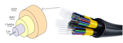
It consists of a very thin fibre of silica or glass or plastic of a high refractive index called the core. The core has a diameter of 10 μm to 100 μm. The core is enclosed by a cover of glass or plastic called cladding. The refractive index of the cladding is less than that of the core (which is a must condition for the working of the optical fibre). The difference between the two indices is very small of order 10-3. The core and the cladding are enclosed in an outer protective jacket made of plastic to provide strength to the optical fibre. The refractive index can change from core to cladding abruptly (as in step-index fibre) or gradually (as in graded-index fibre).
Total Internal Reflection of Light and its Explanation:
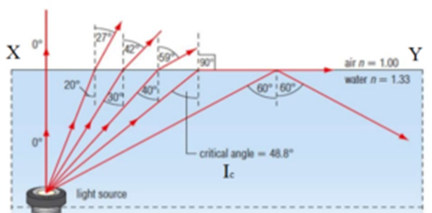
Let us consider a point source O in an optically denser medium (Water or medium with higher refractive index). Let XY be the boundary separating the optically denser medium (Water or medium with lower refractive index). As the angle of incidence increases, the angle of refraction also increases. At a particular angle of incidence iC, the angle of refraction is 90° and hence the refracted ray moves along the surface of water i.e. along XY.
If the angle of incidence is more than iC, there is no refracted ray, the incident ray is completely reflected back in the water (or medium with higher refractive index)). This phenomenon is known as total internal reflection.
The critical angle is the minimum angle of incidence when the total internal reflection of light takes place
Working of Optical Fibre:
When a ray of light is incident on the core of the optical fibre at a small angle, it suffers refraction and strikes the core-cladding interface, As the diameter of the fibre is very small hence the angle of incidence is greater than the critical angle. Therefore, the ray suffers total internal reflection at the core-cladding interface and strikes the opposite interface. At this interface also, the angle of incidence is greater than the critical angle, so it again suffers total internal reflection. Thus, the ray of light reaches the other end of the fibre after suffering repeated total internal reflections along the length of the fibre. At the other end, the ray suffers refraction and emerges out of the optical fibre.
We can see that the light travels in the core in a guided manner. Hence the communication through the optical fibre is sometimes referred as an optical waveguide.
Analytical Treatment of Optical Fibres:
Critical Angle:

By Snell’s law, we have
At the start of the total internal reflection, i = ic and r = 90o
When i > ic, there will be no refracted ray. All incident rays will get internally reflected
Acceptance Angle or Half Angle of Acceptance Cone:
The maximum angle with the axis of the optical fibre at which the light entering propagates through the fibre by suffering repeated total internal reflections at the core-cladding interfaces is called the acceptance angle or half-angle of acceptance cone.
Let us consider a ray of light PQ incident at the air-core interface at angle θi such that it is less than the acceptance angle θa. All the angles are measured w.r.t. the axis of the fibre. The face SR is perpendicular to the axis of the fibre. Let μair, μcore and μcladding be the refractive indices of air, core and cladding respectively such that μcore > μcladding > μair.
Applying Snell’s law at the air-core interface
Where θi = angle of incidence at the air-core interface and θr = angle of reflection at the air-core interface.
Let ∅ be the angle of incidence at the core-cladding interface such that ∅ is greater than the critical angle θc.
From the figure we have
θc + ∅ = 90° hence θr = 90o – ∅
substituting in equation (1)
When θi = θa, then ∅ = θC
This is an expression for the acceptance angle of an optical fibre.
Numerical Aperture of Optical Fibre:
The figure (numerical value) of merit which describes the light collecting ability of optical fibre is called its numerical aperture. Thus light collecting capability of an optical fibre is directly proportional to its numerical aperture.
Numerical Aperture for Step Index Fibre:
The largest possible value of NA is unity
Numerical Aperture for Step Index Fibre in Terms of Relative core-cladding index difference (D)
For an optical fibre, the difference between refractive indices of core and cladding is very small
This is an expression for numerical aperture in terms of relative core-cladding index difference. For graded-index fibre NA = sin θC.
Fibre Attenuation:
Principle of Fabricating Optical Fibre:
Fabrication of optical fibre involves the following two steps:
Step- 1: A glass rod having a definite refractive index is constantly heated by rotating it on the flame of a burner. Silicon tetrachloride vapours are burnt in the same flame so that an oxidized layer of silicon-di-oxide is uniformly deposited on the outer surface of the glass rod. The glass rod is then gradually cooled from 1400°C to room temperature to form a preformed glass rod having different inner and outer glass compositions.
Step – 2: The performed glass rod is then heated in a fibre drawing furnace. The end of the rod is pulled at a constant rate to form a thin fibre containing the core and the cladding. This fibre is then covered with a protective plastic sheath to obtain a fine optical fibre. A bunch of such optical fibres forms optical fibre cable.
Previous Topic: Communication Channels: Wires, Cables, Optic Fibres
Next Topic: Modulation of Signal
3 replies on “Optical Fibre: Principle and Working”
Please clarify whether the core is solid or hollow.
It is a solid fibre whose outer surface is treated such that there is the formation of core and cladding with different refractive indices.
It was really so helpful and easy to understand