Science > Physics > Magnetic Effect of Electric Current > Moving Coil Galvanometer
In this article, we shall study principle, construction, working, sensitivity and accuracy of the moving coil galvanometer
Principle:
When a current-carrying coil is suspended in a uniform magnetic field it is acted upon by a torque. Under the action of this torque, the coil rotates and the deflection in the coil in a moving coil galvanometer is directly proportional to the current flowing through the coil.
Construction of Suspended Type Moving Coil Galvanometer:
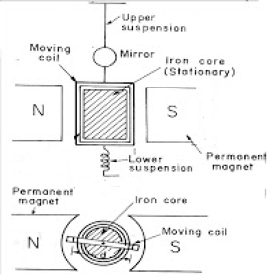
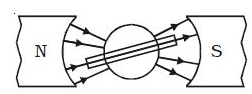
The suspended type consists of a rectangular coil of thin insulated copper wires having a large number of turns. The coil is suspended between the poles of a powerful horseshoe magnet by a suspension fibre of phosphor-bronze. A spring is attached to the other end of the coil. The current enters the coil through the fibre and leaves the coil through the spring. The upper end of the suspension fibre is connected to a rotating screw head so that the plane of the coil can be adjusted in any desired position. The horseshoe magnet has cylindrically concave pole-pieces. Due to this shape, the magnet produces radial magnetic field so that when coil rotates in any position its plane is always parallel to the direction of the magnetic field. When current flows through the coil it gets deflected.
A soft iron cylinder is fixed inside the coil such that the coil can rotate freely between the poles and around the cylinder. Due to the high permeability, the soft iron core increases the strength of the radial magnetic field. A small plane mirror M is fixed to the suspension fibre. This along with lamp and scale arrangement is used to measure the deflection of the coil.

Theory:
Consider a rectangular coil PQRS of single turn having length ‘l’ and breadth ‘b’ suspended in a uniform magnetic field of induction B such that the plane of the coil is parallel to the magnetic field. Let ‘I’ be the current through the coil.
The sides PS and QR being parallel to the magnetic field do not experience any force, but the sides PQ and RS being perpendicular to the magnetic field experience force. The force experienced by each side is given by
F = B I l
By Fleming’s left-hand rule these forces are opposite in direction. As these two forces are equal and opposite they form what is called as a couple and due to which a torque acts on the coil which tries to deflect the coil. The deflection torque is given by,
Torque = Force x Perpendicular distance between the forces.
τ
= F x b
∴ τ = B I l × b
But l τ b = A, the area of the coil
∴ τ = B I A
If the coil has ‘n’ turns, then the deflecting torque is given by
∴ τ = n BIA
Under the action of this torque, the plane of the coil rotates through an angle θ before coming to rest. Due to the radial magnetic field, the plane of the coil is always parallel to the direction of the magnetic field. Thus at any position, the deflecting torque has constant magnitude. The rotation of the coil produces a twist in the fibre which produces a restoring torque which is directly proportional to the angle of deflection θ.
τ ∝ θ
∴ τ = k θ
Where k is the torque per unit twist (or torsional constant) of the suspension fibre.
When the coil comes to rest i.e. when it attains equilibrium, the restoring torque will balance the deflecting torque. So in equilibrium position of the coil,
Deflecting
torque = Restoring torque.
n B I A = k θ
The quantities in bracket are constant, therefore
∴ I ∝ θ
Thus in a moving coil galvanometer current in the coil is directly proportional to the angle of deflection of the coil.
Advantages of Moving Coil Galvanometers:
- They are not affected by a strong magnetic field.
- They have a high torque to weight ratio.
- They are very accurate and reliable.
- Their scales are uniform.
Disadvantages of Moving Coil Galvanometers:
- The change in temperature causes a change in restoring torque.
- Restoring torque cannot be easily changed.
- There is a possibility of damage to the phosphor bronze fibre or helical restoring spring due to severe stresses.
- Such instruments can only be used for measurement of direct current quantities and can not be used for measurement of alternating current quantities.
Pivoted Type Moving Coil Galvanometer:
Construction :
The rectangular coil of thin insulated copper wires having a large number of turns is pivoted between the poles of a powerful horseshoe magnet. The coil is mounted on a pivot between two supports. The supports are bearings with almost no friction. Two hairsprings are attached one above the coil and other below the coil which controls the rotation of the coil. The two coils are spiralled in opposite directions. Current enters through one coil and leaves through the other. A long pointer is attached to the coil which directly moves over a graduated scale. The whole assembly is fitted in a box with a window through which deflection can be observed.
Note:
The principle, working and theory of pivoted type moving coil galvanometer is the same as suspended type moving coil galvanometer.
Sensitivity of Moving Coil Galvanometer:
The sensitivity of moving coil galvanometer is defined as the ratio of the change in deflection of the galvanometer to the change in the current.
Sensitivity = dθ / di
A galvanometer is said to be sensitive if it gives larger deflection for a small current. The current in moving coil galvanometer is given by
Thus the sensitivity of moving coil galvanometer can be increased by
- Increasing the number turns (n) of the coil,
- Increasing the area (A) of the coil,
- increasing the magnetic induction (B) and
- Decreasing the couple per unit twist (k) of the suspension fibre.
Limitations to Increase in Sensitivity of Moving Coil Galvanometer:
- If the turns of the coil are increased the length of wire and hence the resistance of the coil increases.
- Increasing the area of the coil beyond limit makes the instrument bulky.
- Increase in the number of turns and area of the coil increases the load on suspension fibre. Hence spring higher value of k should be used which decreases the sensitivity of the galvanometer.
- Increasing the strength of magnetic induction leads to an increase in the weight of the apparatus.
- Decreasing the couple per unit twist of the spring leads to a decrease in the strength of the spring.
Accuracy of Moving Coil Galvanometer:
The relative error in the measurement of current is given by di/i. For moving coil galvanometer, the current through it is given by
Thus the error in the measurement of current depends only on the measurement of the deflection in the galvanometer dθ.
For greater accuracy of the galvanometer, the ratio di / i should be small. It is small when the deflection is large. Thus for greater accuracy, the deflection in the galvanometer should be large for small current in it. As the expression of accuracy does not contain the terms n, A, B and k the accuracy is independent of the number of turns of the coil, the area of the coil, the magnetic induction and constant for the spring.
Previous Topic: Numerical Problems on Toroids
Next Topic: Ammeters and Voltmeters
2 replies on “Moving Coil Galvanometer”
It was very useful
exactly but something strange