Science > Physics > Units and Measurement > Measurement of Length, Area, and Volume > Use of Micrometer Screw Gauge
Physics is a science of measurement. In science and engineering, we perform experiments. During experiments, we have to take readings. Thus all these experiments require some measurements to be made. During the production of mechanical products, we have to measure the parts so as to find whether the part is made as per the specifications. Thus measurements are necessary for production and quality control. A measurement is a quantitative description of one or more fundamental properties compared to a standard. To measure length is a very important step during the performance of experiments. Measurement can be done directly or indirectly. In this article, we shall study the use of a micrometer screw gauge to measure length, diameter, etc.
Principle:
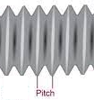
A screw gauge works on the principle of a screw in a nut. i.e. in one rotation screw moves forward through a distance equal to the pitch of the screw. The distance between two successive threads of a screw is called its pitch. Or the pitch of a screw may be defined as the distance that the tip of the screw advances when its head is given one complete rotation. The measurements are done actually through a precisely made integrated screw with a pitch of usually 2 threads per millimetre, which means that on completion of one revolution the displacement achieved is 0.5 millimetre. Screw gauges are more precise than Vernier calipers
Construction:
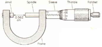
A screw gauge is a device incorporating a calibrated screw that is widely used for the precise measurement of components in the manufacturing of mechanical parts. The body used to hold the anvil and barrel firmly in its place is called a frame, in micrometer screw gauges, thick C-shaped frames are used. It is the fixed part mounted at one end of the frame exactly parallel to the moving spindle which moves towards it. The object whose dimension is to be measured is held between the anvil and the spindle.
The cylindrical part which displaces by rotation of thimble decreasing the distance between itself and anvil until the object being measured becomes stable between the two of them is called the spindle. The stationary part with having a linear scale onto it is called the main scale. It covers the screw mechanism of the screw gauge.
Thimble is the part through which the measuring screw is rotated, this screwing results in the displacement of the spindle and thimble itself. A ratchet is a small device which is used to provide a limited applied force.
A screw gauge has two scales, one rotating scale which can be found on its rotating cylindrical part it is also called a circular scale and the other one can be found on its stationary sleeve which is called the main scale or sleeve scale.
Generally, the least count on the main scale is 0.5 mm. The circular scale is divided into 50 or 100 equal parts.
Least Count:
The minimum length that can be measured using the Vernier calipers is called its least count.

Zero Errors of Micrometer Screw Gauge:
When the anvil and spindle of the screw gauge are made to touch each other, then the zero on the main scale should match with a zero on the circular scale. However due to wear and tear or manufacturing defect the two zeros usually do not coincide with each other, then the vernier is said to have zero error. There are two types of zero errors.
Positive zero error:
If on bringing the anvil and spindle of micrometer screw gauge together, the zero mark of the circular scale is below the main scale line, then the zero error is said to be positive.
To find positive zero error, note the division on the circular scale (C.S.R.) coinciding with the line of the main scale line. Then the positive error is equal to the product of the number of divisions on a circular scale matching with the main scale line and the least count of the micrometer screw gauge. To get the correct reading this error is to be subtracted from the overall reading.
Negative zero error:
If on bringing the anvil and spindle of micrometer screw gauge together, the zero mark of the circular scale is above the main scale line, then the zero error is said to be negative.
To find negative zero error, note the division on the circular scale (C.S.R.) coinciding with the line of the main scale line. Then the negative error is equal to the product of the number of divisions on a circular scale matching with the main scale line and the least count of the micrometer screw gauge. To get the correct reading this error is to be added to the overall reading.
Back-lash Error:
Sometimes the tip of the screw does not move backward for a part of a rotation of the head in the reverse direction, because of the wear and tear of threads. This is called a back-lash error. The back-lash error can be avoided by not rotating the head in the reverse direction once the object is held between the anvil and spindle.
Use of Screw Gauge:
- Hold the object whose dimensions is to be measured between the anvil and spindle of the screw gauge with gentle pressure.
- Note down the main scale reading just before zero of a circular scale. This is called the main scale reading (M.S.R.)
- Note down the number of circular scale division (n) which coincides with the main scale line. Then circular scale reading, (C.S.R.) = n X Least Count.
- Add the M.S.R. and the C.S.R. to get reading.
- Subtract the zero error with a proper sign from the above reading to get the correct reading.
Example: Let us consider a screw gauge with the least count of 0.01 mm.
The main scale reading is 2.5 mm and circular scale reading is 38. Hence the total reading = MSR + CSR x LC = 2.5 +38 x 0.01 = 2.5 + 0.38 = 2.88 mm
To Measure Inside Dimensions:
To Measure Depth:
Micron Micrometer Screw Gauge:
In this case, the least count of the main scale is 1mm, the circular scale is divided into 100 parts and each division on the circular scale is divided into 10 parts.
Least count of the main scale 1mm
Least count of circular scale = 1mm/100 = 0.01 mm
Least count of micron micrometer = 0.01/10 = 0.001 mm = 1 x 10⁻⁶ m = 1 micrometre
Micron micrometre screw gauge can be used for measuring the thickness up to 1 micrometre.
Problems on Use of Micrometer Screw Gauge:
Example 01:
The screw of the micrometer screw gauge moves through a distance of 2 mm when it is turned through 4 rotations. Find the pitch of the screw. If the circular scale is divided into 100 equal parts. Find the least count of the micrometer screw gauge.
Solution:
Distance traveled by screw = 2 mm
No. of rotations given = 4
Pitch of screw = Distance traveled by screw / No. of rotations given = 2mm /4 = 0.5 mm
No. of divisions on circular scale = 100
Least count of the micrometer screw gauge = Pitch of screw / No. of circular scale division = 0.5 mm / 100 = 0.005 mm.
Hence the pitch of the screw is 0.5 mm and the least count of the micrometer screw gauge is 0,005 mm.
Example 02:
If the pitch of the micrometer screw gauge screw is 0.1 mm and its circular scale is divided into 100 equal parts. Find the least count of the micrometer screw gauge.
Solution:
Pitch of screw = 0.1 mm
No. of divisions on circular scale = 100
Least count of the micrometer screw gauge = Pitch of screw / No. of circular scale division = 0.1 mm / 100 = 0.001 mm.
Hence the least count of the micrometer screw gauge is 0,001 mm.
Example 03:
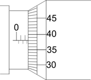
If the pitch of the micrometer screw gauge screw is 0.1 mm and its circular scale is divided into 100 equal parts. Find the correct reading for reading as shown. The no-zero error.
Solution:
Pitch of screw = 0.1 cm = 1 mm
No. of divisions on circular scale = 100
Least count of the micrometer screw gauge = Pitch of screw / No. of circular scale division = 1 mm / 100 = 0.01 mm.
Main scale reading = 4.5 mm
Circular scale reading = 28
Shown reading = M.S.R. + C.S.R. x Least Count = 4.5 + 28 x 0.01 = 4.5 + 0.28 = 4.78 mm
Corrected reading = shown reading – zero error with proper sign = 4.78 – 0 = 4.78 mm
Hence the corrected reading is 4.78 mm.
Example 04:
When a screw gauge with a least count 0.01 mm is used to measure the diameter of a wire, the reading on the sleeve is found to be 0.5 mm and the reading on the thimble is found to be 27 divisions. What is the correct diameter of the wire if the zero error for the gauge is +0.005 cm?
Solution:
Least count of the micrometer screw gauge = 0.01 mm.
Main scale reading = 0.5 mm
Circular scale reading = 27
Shown reading = M.S.R. + C.S.R. x Least Count = 0.5 + 27 x 0.01 = 0.5 + 0.27 = 0.77 mm
Zero error = +0.005 cm = 0.05 mm
Corrected reading = shown reading – zero error with proper sign = 0.77 – 0.o5 = 0.728 mm
Hence correct diameter of wire is 0.72 mm.
Example 05:
When a screw gauge with a least count 0.01 mm is used to measure the diameter of a rod, the reading on the sleeve is found to be 1.6 cm and the reading on the thimble is found to be 48 divisions. What is the correct diameter of the rod if the zero error for the gauge is – 0.003 cm?
Solution:
Least count of the micrometer screw gauge = 0.01 mm.
Main scale reading = 1.6 cm = 16 mm
Circular scale reading = 48
Shown reading = M.S.R. + C.S.R. x Least Count = 16 + 48 x 0.01 = 16 + 0.48 = 16.48 mm = 1.648 cm
Zero error = – 0.003 cm
Corrected reading = shown reading – zero error with proper sign = 1.648 + 0.o03 = 1.651 cm
Hence correct diameter of wire is 1.651 cm.
For More Topics in Measurement of Length, Area, and Volume Click Here
17 replies on “Use of Micrometer Screw Gauge”
I really appreciate this it’s helpful
very very
Very educative
Thanks
Good guidelines, very helpful.
Thanks so much. You are blessed
I have received quite a lot of info. Thanks alot
Thank you plentifully!
I have gained a lot from you!!
Thanks I have gained a certain concept
Thank you so much. I have benefited a lot from this
Great piece of work, so helpful
Weldone
Such a fantastic lessons…. Kudos to the team.
Thank you, for your help and support
Thanks in advance I have gained scientific concepts
Thanks for your help
Thanks sir
Thanks so much